Fluid Loss Calculation
Therefore you want to take that in account when assessing if the patient is at risk for fluid volume deficient OR fluid volume overload. Rate of a specified fluid through a pipe with known length and roughness with specified allowable head loss.
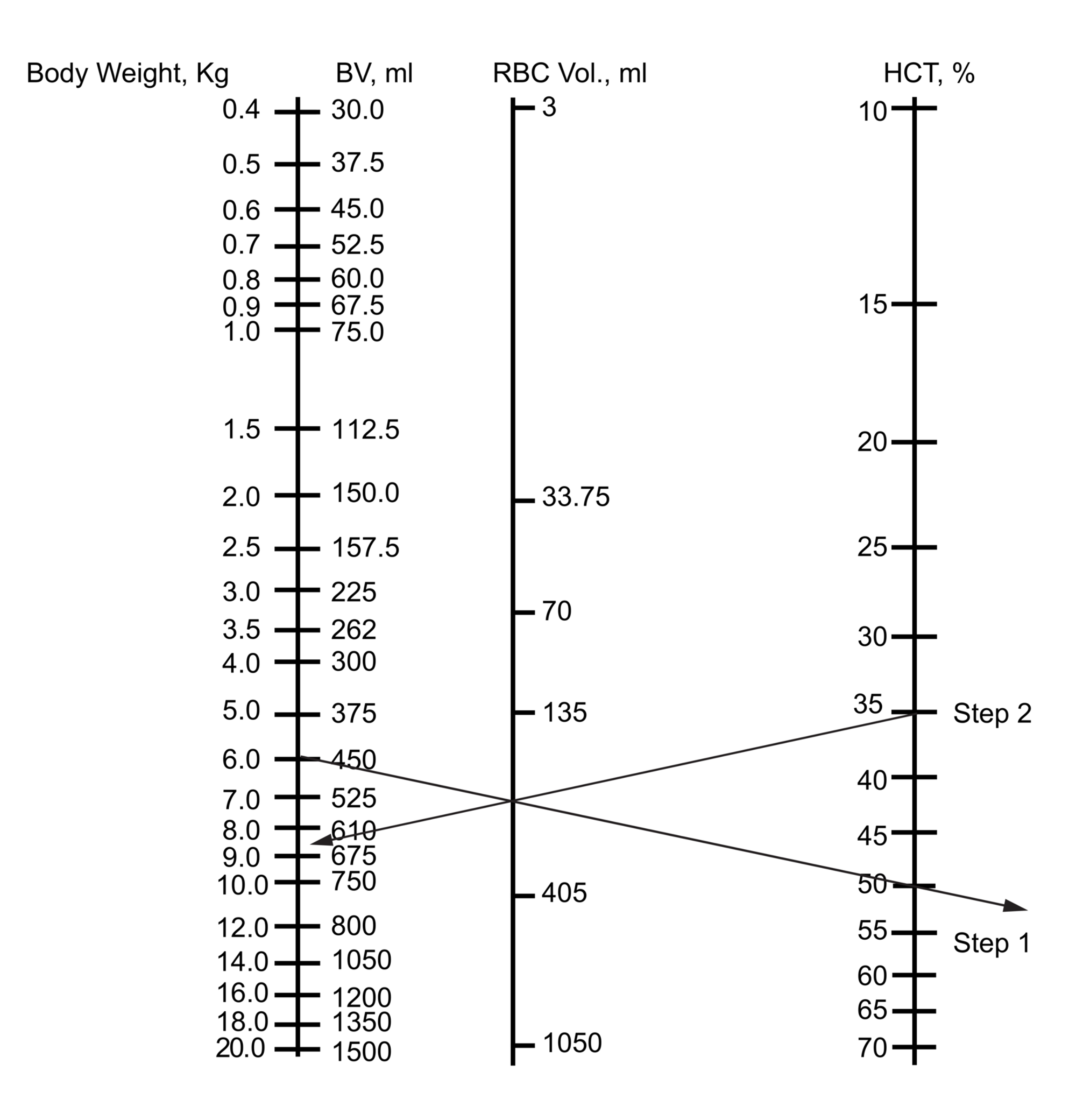
Cureus A Nomogram For The Rapid Prediction Of Hematocrit Following Blood Loss And Fluid Shifts In Neonates Infants And Adults
Clinical Practice Guidelines Intravenous Fluids

Should Holliday Segar Formula Be Challenged
This article details the calculation of pressure losses through pipe fittings and some minor equipment using the K-value method also known as the Resistance Coefficient Velocity Head Excess Head or Crane method.
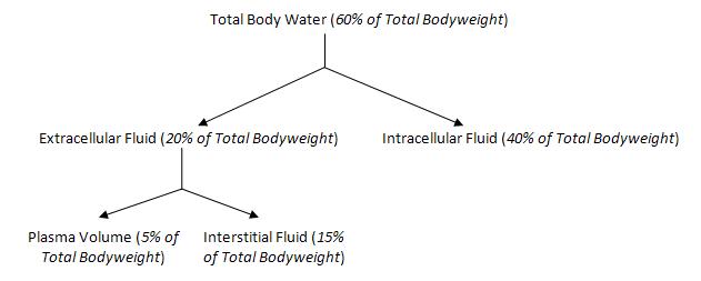
Fluid loss calculation. The percentages of body water contained in various fluid compartments add up to total body water TBW. The equation above is based on the heat loss of an entire flat area where the inside area of the insulation wall is the same as the outside area. It is usually measured as a liquid surface elevation expressed in units of length at the entrance or bottom of a piezometerIn an aquifer it can be calculated from the depth to water in a piezometric well a specialized water well and given information of the piezometers elevation.
Kinetic energy is recovered into pressure energy and loss of energy is less. The pipe flow calculation can compute flow rate velocity pipe diameter elevation difference pressure difference pipe length minor loss coefficient and pump head total dynamic head. Pipe Heat Loss Considerations for Industrial Applications.
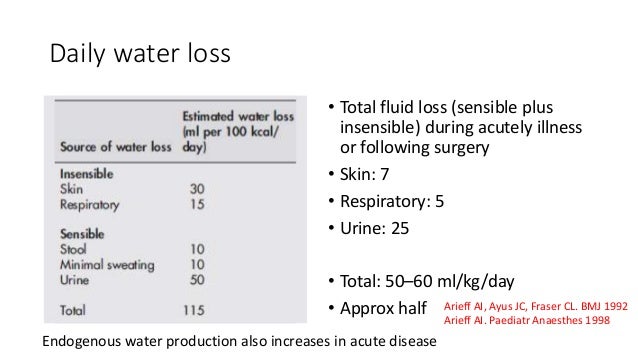
Hydraulic head or piezometric head is a specific measurement of liquid pressure above a vertical datum. Calculation of pressure drop caused by friction in circular pipes. This means that for every 100 kcal burned the patient utilizes 100 ml of fluid.
Pumps - Piping systems and pumps - centrifugal pumps displacement pumps - cavitation viscosity head and pressure power consumption and more. Pump Sizing Calculation Home Fluid Flow Pump Sizing Calculation This tool does hydraulic calculation for a pump and estimates differential head hydraulic power motor power NPSH available. Other factors such as mechanical efficiencies fluid dynamics and material limitations must also be considered.
Sweat rate varies depending on factors such as environmental conditions exercise type exercise intensity and. Continuity Equation describes the transport of some quantities like fluid or gas. Major losses are associated with frictional energy loss that is caused by the viscous effects of the fluid and roughness of the pipe wall.
Energy Loss in Pipes 1. Power is consumed by a pump fan or compressor in order to move and increase the pressure of a fluid. Flow separation eddies formation creates due to loss in energy.
The Bernoulli equation energy equation calculation does not check for unreasonable inputs such as negative density negative velocity or pressure less than a complete vacuum. Heat Exchanger Rating Bell-Delaware Method Heat Exchanger Analysis ε. Spent estimate monthly estimate Monthly progress payment integrated converter of the estimate under all types of currencies international market Assessment of work Statistics analyzes graphic synthesis.
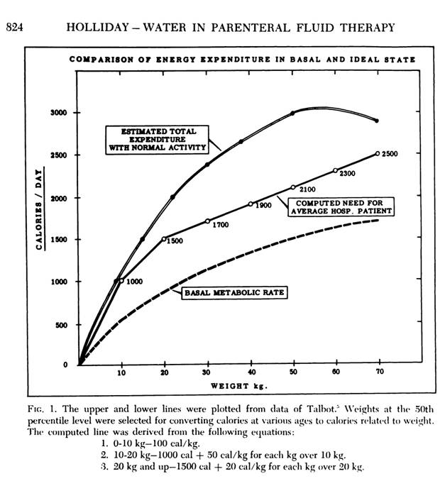
Total daily water requirement to replace insensible and urinary water loss in the hospitalized patient is approximately 100 ml100kcalday. A side effect of sweating is the loss of valuable fluids from the finite reservoir within the body the rate being related to exercise intensity individual differences environmental conditions acclimatization state clothing and baseline hydra-tion status. In physiology body water is the water content of an animal body that is contained in the tissues the blood the bones and elsewhere.
The continuity equation in fluid dynamics describes that in any steady-state process the rate at which mass leaves the system is equal to the rate at which mass enters a system. To simplify heat loss calculations pipe heat loss is based on the heat loss per linear foot rather than the entire area of any given length. Spreadsheet for typical fluid flow calculations like single phase fluid flow in a pipe.
To determine the fluid liquid or gas pressure drop along a pipe or pipe component the following calculations in the following order. The power requirement of the pump depends on a number of factors including the pump and motor efficiency the differential pressure and the fluid density viscosity and flow rate. Converting Pump Head to Pressure and Vice Versa - Converting head ft.
This varies depending on the patients activity level temperature etc. The diffuser is angle about 5 to 7 and this low angle helps not to separate the flowing fluid from the boundary. Changes of kinetic energy.
The density and viscosity of a variety of liquids and gases are coded into the pipe flow program but you can alternatively select User defined fluid and enter the density and viscosity for fluids not listed. Subsequent fluid therapy is calculated as follows. Line Sizing Single Phase Fluid Flow.
Calculation include safety valve sizing and. Advanced Fluid Systems has taken great care to verify that the. Air cooled exchanger lmtd calculation lmtd correction factors insulation heat loss and jacketed vessel heat transfer.
While fluid power formulas are useful tools for specifying system components and capabilities. Calculation include pressure losses in pipe and fittings natural gas pipe sizing. The loss term h L accounts for all minor valves elbows etc and major pipe friction losses between 1 and 2.
The calculation shows a head loss of 846 feet of fluid. Athletes whose sweat loss exceeds fluid intake become dehydrated during. According the Mosbys Medical Dictionary insensible loss is estimated to be 600 mLday insensible water loss 2018.
Involves velocity pressure density and temperature as functions of space and time. Of this 200 ml has already been infused in the ER so the remaining deficit is 800 ml. Fittings such as elbows tees valves and reducers represent a significant component of the pressure loss in most pipe systems.
This article provides relationships to determine the required pump power. Since this pipeline was calculated with a flow rate of 400 gpm this example will calculate the head loss for 200 gpm and 800 gpm through the same 100-foot section of 4-inch steel schedule 40 pipe. Next we will determine what happens when the flow rate is changed.
Heat exchanger analysis and heat loss from insulated pipe. For Bernoulli applications please see our Bernoulli Calculator with Applications. The total energy loss in a pipe system is the sum of the major and minor losses.
Fluid Mechanics - The study of fluids - liquids and gases. Vertical pipe difference or elevation. Be able to use the Darcy Weisbach equation and the Moody friction factor equations to calculate the fluid flow rate through a pipe with known diameter.
This childs total fluid loss was 10 of 10 kg or 1000 ml. Quotation program on Excel. Pressure drop in pipes is caused by.
The Fluid Loss Calculator is an estimate of an athletes hourly sweat rate during exercise. This tool is useful for assessment of fluid losses during exercise based on changes in body weight. By this time serum electrolyte levels are available and the serum sodium concentration is within the normal range.
Look at the basic part of. This water makes up a significant fraction of the human body both by weight and by volumeEnsuring the right amount of body water is part of fluid balance. Conclusion This experiment can conclude that A Venturi meter can be used to determine the flow rate in the pipelines and the pressure loss that occurring in order to control the discharge fluid addition to the discharge coefficient of a Venturi meter.
Water loss and therefore water requirement is a function of caloric expenditure.
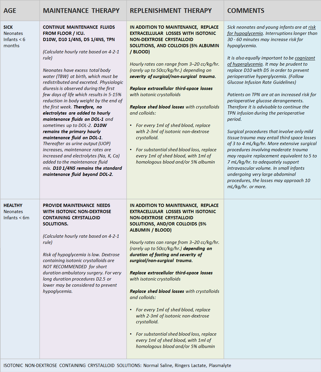
Fundamentals Of Perioperative Fluid Therapy Pediatric Anesthesia Digital Handbook

Calculating Fluid Deficit In A Sick Child Nursemathmedblog

Fluid Calculations Keeping A Balance Today S Veterinary Nurse

Fluid Balance In Children Ppt Video Online Download
Principles Of Fluid Therapy Wikivet English
2
Normal Maintainence Requirements
Calculation Of Fluid Loss Or Gain
0 Response to "Fluid Loss Calculation"
Post a Comment